Control
There will be 3 modes of operating, all ultimately using Infra-red signals beamed to the locomotives.
The message broadcast to the locos are simply made up out of 3 characters sent via the RS232 port of the chips..
- A star (*) - to mark the beginning of the data stream
- The Loco ID (send as one ASCII character) to specify a single loco, or 255 to specify "Any/All" locos
- An instruction number (sent as 1 ASCII character). Examples: 1=Stop, 2=Shunt forwards, 9=Whistle, 11=Couple etc
The data is sent out of the RS232 port of the chip, but is sent at TTL levels rather than the traditional RS232 voltages.
The three modes are outlined below.
Handset
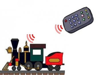
The first method will be by a hand set. The handset will beam out instructions to the loco telling it what to do. The loco will receive the signal from a receiver mounted somewhere on the top, and will complete the task requested. The current handset can control locos 1-3 or "all/any" locos within sight of the transmitted beam.

Levers
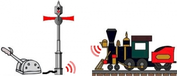
Next, signals will have a manual set of switches (or a lever) directly connected to them. By pressing a switch, the appropriate control code will be transmitted out of the signal. This signal will be addressed to "Any/All" locos, so any train within sight of the IR beam will respond to the request.

Fully Automatic
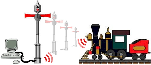
Finally there will be one "Master" chip that will contain a whole sequence of signal events. The Master chip sends out a message to all the signals, but also sends out a signal ID, and a Loco ID. The signal that matches the signal ID will respond and send out a signal to the loco with the Loco ID.

The Master chip broadcasts a data stream made up out of the following units
- A star (*) to mark the beginning of the data stream
- A Signal ID to specify which signal should respond. If 255 is sent, ALL signals will respond.
- A Loco ID which is then transmitted by the signal
- An instruction. If a regular Loco ID is transmitted, the the action is also transmitted. If the Loco ID is zero, then the signal will use the action command for itself (to change it's lamp output or to move the signal arm).
- A flag to indicate the end of the stream, or that more instructions are to follow.
If more instructions are to follow, then the next sequence starts at part 3 as it is assumed the specified signal is still listening. Up to 5 instructions can be strung together
So a typical data set might be
* 1 0 9 + 1 3 # (the ASCII codes are shown here, not the characters)
Meaning Hello, signal 1, loco 0 (the signal), change from red to green, AND Loco 1, shunt forwards, end
or * 255 255 1 # = ALL signals send to ALL locos "STOP" (this is always the first instruction send by the master chip)
Copyright of the images above belongs to the original copyright owner, to which I thank as they brighten up this complex text.