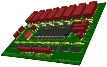
Control Board Design
Article #22 - 25/10/2021 23:53The slave control board will talk to the main control unit via the SPI bus.
Each of these boards have the following...
8x DPDT relays - these will connect/disconnect power to track zones, and swap between red/green signal LEDs for that zone.
8X Power MOSFET diodes for switching power to the point motors from the Capacitor Discharge Unit. (2 ways for 4 points)
8x General I/O ports for general use - 2 of which can be PWM outputs.
Comms via the SPI bus or via Bluetooth via the RS232 port.
Ability to have a stored sequence for automatic running.
2 of these units will be required for the main loops - with another to be used for the inner areas such as the traverser & turntable.
.jpg)
.jpg)
.jpg)
.jpg)
.jpg)
.jpg)
.jpg)
.jpg)
.jpg)
.jpg)
.jpg)
.jpg)
.jpg)
.jpg)
.jpg)
.jpg)
.jpg)
.jpg)
.jpg)
.jpg)
.jpg)
.jpg)
.jpg)
.jpg)